Porous Plugsa New Generation of Fluxing and Purging Technology
in the Aluminium Industry!
透气砖
铝工业新一代除气精炼技术
Dipl. Ing. Reinhard Schwaiger
Marketing Department Non Ferrous metals
RHI AG – Non Ferrous Engineering GmbH
Some years ago, due to several misconceptions as, danger of leaking metal and gas, deterioration by Cl2 , easy irreversible blindness etc. to put a plug, which is porous into the bottom of a Aluminium furnace was nearly unthinkable. - To install more than a dozen of them in a molten metal furnace seemed to be impossible.
Necessity, however, is the mother of invention and persuasion.
When beginning to design work on the casting facilities of a Aluminium plant, some challenging fluxing and stirring goals for the furnaces had been established.
These goals were far beyond the capability of the standard handheld fluxing wands (lances) which had been used for so many years.
一直以来,人们出于对炉底漏铝事故,氯气腐蚀管道,管道被熔液倒灌等事故的担心,对冶炼铝金属的炉底使用透气砖这一技术产生过疑惑和误解,使得在炉底安装透气砖这一构想一直停留在想象阶段-----要在熔炼炉、混合炉内安装多个透气砖进行吹气搅拌听起来更显得不切实际。
然而,正是对生产工艺精益求精的需求,激励着工程师和科学家不断创新,让构想变成了今天的现实。
从着手设计生产线开始,一连串提高质量和降低成本的目标摆在了我们面前,这些标准对于多年来习惯使用的造渣棒或者喷射枪进行熔炉除气的传统技术来说,几乎无法达到的,随着底吹透气精确控制工艺的问世,使得一系列的改善标准得以实现。
目前,在国外铝材熔炼以及铸造行业已经广泛地在各种炉底安装多孔透气砖及相应的气体配送调节系统进行有序的底吹搅拌,然而在国内冶炼行业由于接触国际市场比较晚,这项引进工作才开始不久,这一技术为铝铸造行业带来的是革命性改善:
The goals were:
目标:
- Improve fluxing quality提高搅拌质量
- Decrease flux time by 50%降低搅拌气体耗时50%
- Decrease Cl2% of flux gas减少搅拌气体中氯气的用量
- Improve melt rate提高排气效率
- Decrease emissions减少气体排放(包括有毒气体)
- Pre-treatment of the metal实现金属预处理
- Improve thermal homogenization大大改善热循环,炉内温度更加均匀和谐
- Improve degassing efficiency提高熔解速率
- Reduce of thermitting dross减少铝渣析出
- Long life and Low maintenance耐用且维护费用极低
- Reach across the whole melter?s bottom area搅拌幅度深达炉底
Porous plug technology offered the best opportunity to achieve these design goals. - A program to develop a practice for installing and applying plugs in Aluminium furnaces had been initiated.
Basically, porous plugs have been used in the industry for bubbling flux gas through molten aluminium baths for degassing and stirring. Early successes were realised in flux boxes and smaller applications. Serious attempts to apply the technology to furnaces were not made until the late 1980’s.
多孔透气转搅拌技术在早期被成功的应用在转铝包和在线除气箱上,直到上世纪九十年到初才涉足尝试应用于真正的混合炉和熔解炉底部吹入气体作为除气熔剂和搅拌介质,进行除气精炼。
1.Description of the APA - Porous Plug design:
APA型透气砖设计描述
The latest Plug design is designated APA and is one of the largest porous plug designs manufactured by RHI.
The current design, shown in Figure 1, is comprised of a round reverse tapered porous refractory core (A) shrouded (shrieveld) by a metal can.(C) (Inconel or SS ) The can is continuous across the bottom of the plug and up the sides with gas tight welds. A metal (Inconel or SS) flux gas supply pipe (D) passes through and is welded to the can bottom and extends into the porous core material. Around this assembly is a refractory nest block (B) to serve as protection for the porous media and as an interface with the furnace bottom refractory.
A detached but very critical component of the plug is the external packing gland (E) which is welded at the furnace bottom. This unit provides a gas tight seal around the flux gas supply pipe when it exits the furnace bottom.
APA型透气砖是RHI公司所生产的最大的透气砖。
如图一所示,透气砖砖心(A)由多孔性锥型的耐火材料和(C)包裹在透气砖周围紧密连接的不锈钢壳或镍铬合金,钢壳从底部到侧部使用气密性焊接。透气用的钢管(D)通过底板从底部通入气体到达透气砖芯。砖芯外围包裹一层预制成型的浇注料保护层,称之座砖(B),主要用于保护透气。还有一个重要的单独的零配件是(E)密封衬套,焊接在底部钢板用于紧密送气管和炉壳之间的密封,防止任何气体从炉内逸出。
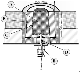
Fig. 1: APA- AL-KIN PLUG Assembly
In operation, gas enters the plug assembly bottom via the supply pipe and disperses in the porous core.
The porous core of the plug is a pressed and fired Corundum - chrome material. The final shape is a dense, aluminium resistant unit with a texture much like that of a common high Alumina brick. The porous characteristic is derived from grain size engineering and pressing techniques.
The finished porous core is 330 mm deep which places its bottom below the freeze plane in most furnaces. The non-porous refractory liner, - the nest block is a high strength Corundum – Spinel pre-cast and pre-fired shape.
在实际应用中,气体进入通过送气管进入分散到多孔的砖芯里面。砖芯材质为压缩和烧结的刚玉氧化铝-铬,外形像一块致密且带纹理的不黏铝的刚玉高铝砖。其透气特性主要来自原材料特殊的结晶颗粒筛选工艺和静压力成型压砖工艺
成品多孔透气砖高330毫米,安装时底部将处于铝液冻结等温线平面以下。 - 非多孔耐火材料内衬,是一种高强度刚玉 - 尖晶石预制和预焙烧的成型的。
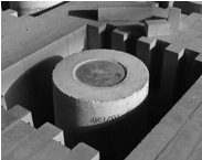
Fig. 2: APA Plug .APA透气砖实物照片
Additional, available Plug designs:
其他尺寸的透气砖:
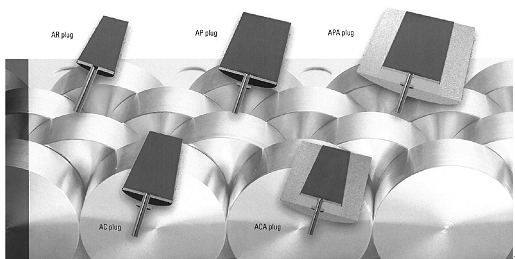
Application:
应用:
|
APA ACA (changeable ) |
|
|
AP; AC |
|
|
AR; ARH |
|
2. Melter and Holder Plug Layouts:
熔炼炉保温炉使用透气系统特点:
2.1 Melters 熔炼炉
Customer Requirements - Melters : 客户要求:
-
Improved Melt Rate
提高熔铝速度 -
Less Time required to achieve Alloy Chemistry
合金调配时间短 -
Pre-treatment of the metal
金属预处理 -
Reduction of dross build up
较少炉内积渣 -
Low Maintenance
少维护 -
Reasonable Cost
价格合理 -
Long Life
使用寿命长
|
|
|
|
Fig. 3: 48 MT Round Top Charge melter 48吨圆形熔炼炉 |
Fig. 4: Melter - Plug Installation Detail |
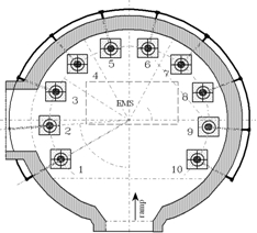
Figure 3/4 show a 48 ton, top charging melter. The bath level of molten Aluminium is 650 mm deep and is equipped with 10 plugs arranged around the periphery. The purpose of the plugs in the melters is primarily to reduce dross build-up on the wall at the bath line, although the melter metallurgical practice requires a brief flux at alloys.
Some of the melters are equipped with electromagnetic stirrers mounted beneath the bottom steel. Though this device is intended primarily for stirring, it does an effective job of distributing the periphery plug bubbles to the bath interior.
10块透气砖围绕着边上安装是为了减少炉墙周围边上的积渣。
如果有些熔炼炉安装了电磁搅拌,透气砖的管路可以按照在耐材的隔热保温层,不影响底部电磁搅拌的安装和正常工作。
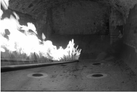

2.2 Holders 保温炉
Customer Requirements - Holders : 客户要求:
-
Improved Degassing Efficiency
提高除气效率 -
Improved Thermal Homogenisation
提高热同步 -
Less Dross
较深烧损 -
Low Maintenance
少维护 -
Low mechanical Damage of installed Refractories
没有任何机械磨损 -
Reasonable Cost
性价比突出 -
Long Life
使用寿命长
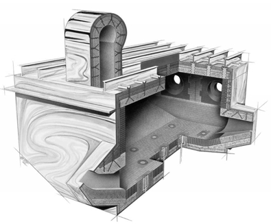
Fig. 5: 130 MT
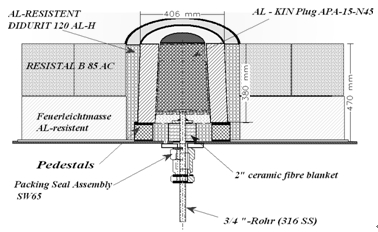
Fig. 6: Holder (Tilter) Plug Installation Detail
透气砖整体装示意图
Figure 5 shows a 130 ton CASTER. The bath level is 1220 mm deep and is equipped with 24 plugs arranged in 3 rows.
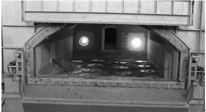
Fig. 7: Holding furnace: 14 porous plugs in operation
3 Conclusions on Porous Plugs Performance
透气砖优势总结
TOP 10 OPERATION TRUTHS:
十大优点:
|
1.Excellent degassing tool |
2.Operator friendly |
|
3.Decreases fluxing time |
4.Decreases CL2usage |
|
5.Eliminates bath temperature stratification |
6.Decreases thermitting dross |
|
7.Generates less dross |
8.Decreases emissions |
|
9.Pre-treatment of the metal |
10.Improve thermal homogenization |
From years of operating experience, can be stated with a knowledgeable certainty that the above are credible conclusions for porous plugs applied to can stock alloys 3104 and 5182 as well as rigid container alloys.
Number 1 on importance list is the metal treatment quality being realised with the plugs. Tests have indicated hydrogen levels in the bath immediately following fluxing to be reduced up to 50% compared to levels achieved by standard fluxing wand practices. Particulate counts also appear to be improved despite significant reductions in settling times which had been implemented.
根据多年的运营经验,可以确定地说,上述是透气砖系统效能的结论适用于易拉罐合金3104和5182以及刚性容器合金。
最总要的一点是透气砖提升了金属处理的质量。测试结果表明使用透气砖比起使用传统的插入式精炼喷枪将氢含量马上降低达50%。颗粒计数也出现改善,但在解决已实施的时间显著减少。操作和处理时间也相对减少, 因为操作透气砖只需要轻按按钮。
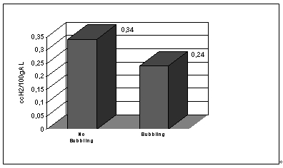
Fig. 8: Typical pre-treatment results. Hydrogen concentration in melters
熔炼炉中合金预处理结果,氢含量比较,左边是使用透气砖,左边没有透气砖
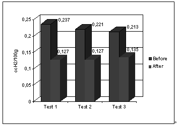
Fig. 9: fluxing results with porous plugs, 16 MT Holding furnace,
Alloy 3003, 12 Plugs 100% Argon, 30 min fluxing
16吨保温炉,12块透气砖通入100% 氩气,冶炼3003合金
The advent of porous plugs at Alloys Plants has allowed furnace fluxing to become a pushbutton operation. The operator sets the desired flux flow rate on the control screen, starts the flux and visually checks the appearance of the bath surface. He may choose to adjust the flow to an individual plug if the bubble appears incorrect. The flux continues for a pre-set duration, after which the flux is automatically terminated and the purge cycle is begun. This closed door fluxing practice allows the furnace fluxing to proceed with minimum levels of oxygen and moisture from the atmosphere entering the furnace.
The holder flux time significantly decreases while achieving greater fluxing quality performance. The porous plugs have allowed to reduce the fluxing time significantly compared to hand-held flux wands while lowering the chlorine content of the flux gas as well. The reduced CL2content and the more efficient fluxing bubble likewise reduce stack emissions from the holders with significantly lower amounts of free CL2 and particles.
在合金工厂多孔透气砖的问世,使炉精炼成为一个按键操作。操作员设置所需的透气流量通过控制屏幕设定,通入气体并检查铝溶液表面的流动。如果涌起的泡沫出现不正确,操作员可以调节单个透气砖的流量。通过预先设定的精炼时间,完成后系统自动终止,然后周而复始的自动运行。全过程紧闭炉门的精炼方式,把空气和水汽排除在炉内环境以外,使炉内铝业进行氧气和水分吸收降低到最低水平。
保温炉精炼的时间显著减小,同时实现更高的精炼效果。多孔透气砖,与手持式精炼喷枪相比,降低精炼气体的氯气含量以及,减少氯气化合物排放和更有效的吸收精炼气泡,使得剩余的氯气和粒子由烟囱排放显著降低。
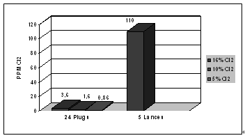
Fig. 11: Chlorine Emissions, Holding furnace (100 MT),
Total Gas Consumption per, flux : 18 litres
100吨保温炉氯气排放,24块透气砖一次精炼,使用氯气气体18升
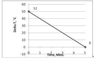
One of the most significant benefits of the plugs in the holding furnaces has been their capability to eliminate temperature stratification. A relatively uniform holder bath temperature is necessary for the casting process, and the deep holder bath (1220 mm) creates a problem in this area. As the burners fire, the surface temperature begins to rise while the temperature at the bottom of the bath may continue to fall until a spread of 10°C to 40°C or more exists. Figure 12 represents a period of holder operation and plots the upper and lower thermocouple temperatures through a firing and purge cycle. During this short purge, a temperature differential of 50°C was reduced to less than 5°C in less than five minutes without opening the furnace door. These readings were taken with 100 Ton of molten metal in the furnace.
保温炉透气砖的最显著的优点之一,在于它消除铝液温度分层。对于铸造来说,一个相对均匀统一熔池铝液温度在铸造过程中是必需的,然而较大的熔池深度(1220mm)给均匀温度带来了困难。由于燃烧器火焰直接加热到铝液的表面,表面温度开始上升,而在熔池底部的铝水由于底部散热,温度可能会下降,导致上下之间10° C至40° C的温差存在。图12所示,使用透气砖进行底吹精炼,在不到五分钟内,上下层液面的温差由50° C降低到小于5°,整个过程无需打开炉门。这些数据来自100吨熔化炉内熔化的金属。
 s
s
Fig. 12: Thermal homogenisation, Tilter (100 MT),
24 Plugs / 14 l / min each, metal depth 1220 mm
100吨倾翻炉 通过24块透气砖,炉液面深度1220mm,热同步处理
Possibly the most noticeable visual difference in porous plug versus wand fluxing is the amount of dross produced and the absence of thermitting dross. A study of dross generation performed by the RMC Manufacturing Technology Laboratory covering 14 cycles of 3104 alloy indicated an average dross generation of 0,7% of the molten charge weight during a complete holder cycle. Dross generation in holding furnaces with wand fluxing averaged more than twice (1,5%) and historically was a light thermitting dross which required mechanised cooling and provided poor recovery.
直观上,透气砖精炼与传统喷枪精炼最主要的差别在于减少造灰渣和降低烧损。在RMC铝厂测得14次出炉数据,冶炼3104合金,我们获得的以下结论:使用透气砖精炼比起使用喷枪精炼降低0.7%的烧损。而且这些减少的铝渣多为轻质灰渣,不可再生回收利用。
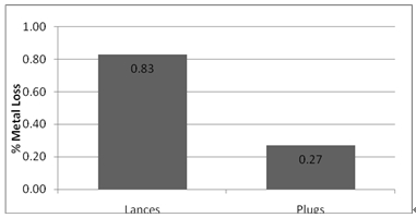
Fig. 13: Dross Savings, 24 Plugs versus. 5 Lances
烧损
Dross from holding furnaces with plugs is generally a cold dross with an estimated recovery of 60% .The dross may be charged directly into Rotary Barrel furnaces. thermitting dross, even with high magnesium alloys, is virtually non-existent and allows discontinuation of mechanised cooling .
The singular basic difference is the existence of the porous plugs and the hourly purging practice. It follows that elimination of the thermiting dross is directly attributable to the porous plugs, the bath temperature uniformity realised with them, and the ability to flux with the furnace doors closed.
Good flow controls and purging practices are necessary to assure long-term use of porous plugs. A system which will feed either flux gas or nitrogen to a pneumatic flow control valve at a regulated pressure should be installed. Flow is measured via an orifice plate metering run with a differential pressure transmitter providing feedback to the control loop.
使用透气砖精炼产生的渣多为冷渣,可以直接放到球磨机提炼后重熔,回收率一般达到60%,而热灰渣虽然镁含量高些,几乎看不到金属存在,的回收率很低。
烧损的降低主要归功于透气砖能够使温度同层均匀,减少表面过度加热造渣;全过程关闭炉门操作避免了空气进入。
精确的流量控制对于达到长期良好的精炼效果至关重要。系统必须持续提供稳定而可控的气流量,不管炉内工作压力如何因为液面高低变化,气流量始终保持在设定值,不能波动。 这需要比例调节阀和流量测量形成的回路控制。
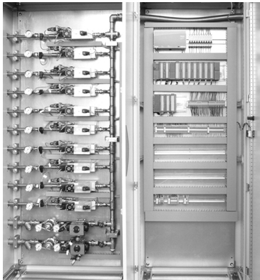
Fig. 14: 10 line Flow Control Panel with individual mass flow meter
10 线气体控制柜
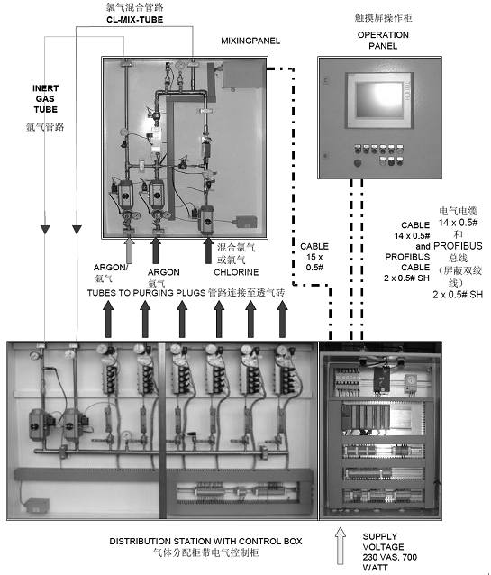
Figure 15
带氯气/氩气氮气混合柜的气体控制系统
Porous Plugs water models:
多孔透气砖水箱模拟模型:
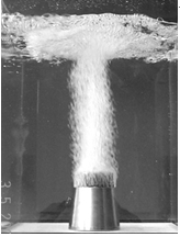
The improved quality may be explained by water modelling studies performed by the Reynolds metallurgical Laboratory(USA). Figure 16 depicts the currents created in a 1220 mm deep tank from the bubbling action of one plug mounted in the bottom. The model indicates the optimum flow for degassing to be approximately 12 - 14 l /min for a Model APA-20 plug. At this rate the bubble pattern is most stable and creates the least amount of surface disturbance. At higher flows, counter currents generated by the vertical column and surface disturbance can actually entrain gases and particles from the surface and draw them down into the bath.
雷诺兹冶金实验室(美国)的水模拟研究可以解释透气砖如何提高搅拌效果。图16显示了在1220毫米深的水箱底部安装一个插件可以透过压缩空气的透气砖。该模型表明,就一个型号APA- 20透气砖而已,除气精炼中最佳流量约12 - 14升/分钟。泡沫的图案表面,在这个流速是最稳定和使得表面扰动量最少的。如果继续调整到更高的流速,气泡变成垂直气柱和表面扰动所产生的反回流,会从表面的把铝渣和杂质重新带到铝液中。
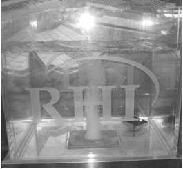
Fig. 16: Water Model Depiction of molten metal currents
4.Discussions of water models for porous plugs:
水箱模拟模型研究:
4.1 The process: 过程:
Inert Gas (mixed with Chlorine or pure ) is injected at the bottom of the porous material, and enters the liquid metal in form of bubbles.
In the metal, the gas reacts with elements in the metal and induces the metal to flow.
The effectiveness of the reaction is determinated by the gas fluid interface and residence time of the bubbles in the melt. The effectiveness of the stirring action is determined by the interaction between the gas and the liquid phase. Therefore, the following parameters are of importance.
惰性气体(混合氯气或纯气体)通过弥散式蜂窝透气砖,以气泡的形式从熔池底部直接吹入铝金属熔体内。
在铝金属熔液内,气泡直接接触到金属反应并形成金属液体流动。熔体与气体反应的程度主要取决于气泡跟铝液之间接总触面大小和气泡在铝液中停留时间,流体被搅拌的强度主要取决于气相和液相之间的相互作用,因此以下的参数变得非常重要。
4.2 Gas flow regimes: 流谱曲线
Different regimes are observed for different gas flow rates, each with its own characteristics. For low gas flow rates, discrete bubbles form at the plug surface. At intermediate gas flow rates, the bubble frequency increases due to the fact that dormant pores in the plug get activated. Then, bubbles start to coalesce, become larger and eventually, the bubble pattern becomes completely chaotic.
不同的气体流量产生不同的气流模型,每个模型具有各自的流体力学特征。
对于低流速情况下,气泡从透气砖表面溢出,呈现不连续离散式分布;
对于中等流速情况下,气泡数量呈现增加趋势,因为更多原来不通气的弥散式气孔开始冒气工作,使得透气砖表面气孔使用率增加;
继续增加流量,我们发现小气泡之间开始接合成大的气泡,继续结合成更大的气泡,最后气泡图案变成彻底的无序的紊流图案。大气泡与铝熔液接触的表面积相对于原来多个小气泡减少了。
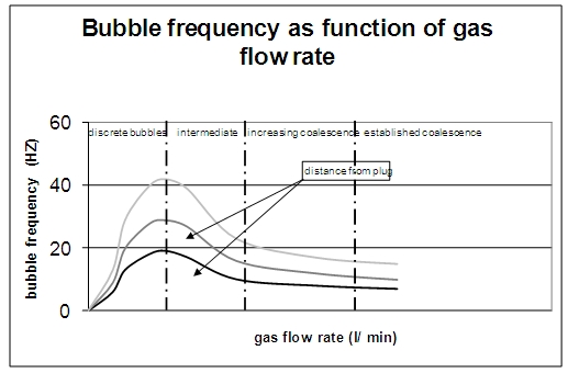
Figure 17. Variation of bubble frequency as a function of gas flow rate
at various heights above the plug.
气泡总数量相对气体流速的变化曲线。不同颜色代表测量点离透气砖表面不同的距离(深度)
|
|
|
|
|
discrete bubbles |
Intermediate |
Chaotic |
4.3 Gas fraction distribution: 气泡分布:
From water model experiments it is known that the gas fraction within the plume is bell shaped for all regimes. Increasing the gas flow rate widens the gas fraction profile and the gas fractions become larger. As an indication the data described in (1) where watermodel experiments on a 60 mm diameter porous element in a liquid bath of 400 mm water. For the discrete bubble pattern the fraction is found to be 0.4 close to the plug and decreases to 0.05 close to the surface. The gas fraction for different heights can be formulated as.
从水箱模型观察可知,不管哪个流速状态下,气体气泡在水中分布均呈现上小下大的钟型分布,增加气体单位时间气流量将使得气泡分布更宽,而且气泡的体积也变得更加大。从以上水箱模拟模型我们发现,把直径60mm的透气砖放到400mm见方的水箱中,不连续的气泡在靠近透气砖表面地方是0.4,到靠近液体表面时接近0.05。
气泡大小与气体流速的关系可总结为以下公式:
? = 0,71 ( z/ ([Q2/ g ]0,2))0,9
4.4 Bubble frequency: 气泡数量:
In characterising the interfacial area between melt and gas, the bubble frequency within the plume is an important parameter. For the discrete bubble pattern the bubble frequency lies in the order of 100 Hz close to the plug. Close to the surface, the bubble frequency decreases to 10 Hz. The development of the bubble frequency as a function of the gas flow rate is shown in Figure 1. Increasing the gas flow rate initially causes the bubble frequency to increase, activating dormant pores. But for higher frequencies, the bubble frequency reaches a maximum. A further increase of gas flow causes the bubbles to coalesce to larger bubbles, thus reducing the bubble frequency and also reducing the interfacial area.
上升过程中气泡频率(单位截面下的气泡的总数量)是气态气泡和液态金属之间的接触面大小的决定性因素。
离散式不连续气泡模型下,气泡离开透气砖编码时频率为100Hz,频率随着气体流速增加的变化曲线如 图17 所示: 增加流速一开始可以增加气泡频率,把原来处于休眠状态不工作的孔激活到工作状态,更多气泡冒出。但如果想通过增加流速达到更高的气泡频率,我们发现气泡频率达到一个最大值。再继续加大气体流速只会使得气泡变得无序,然后那些靠近的气泡会融为一体成一个大气泡。这只会降低气泡频率从而减少气体和铝业的总接触面。
4.5 Bubble velocity: 气泡上升速度:
A large bubble residence time in the melt can be necessary for a good reaction between gas and melt. Therefore, the bubble rise velocity is of importance.
Increasing the gas flow rate from the discrete bubble to intermediate regime causes an increase in bubble rising velocity. This indicates that the interaction between bubbles becomes important. Increasing Q = 0.72 m? /hr to Q = 2,16 m? /hr gives an increase from 1.05 m/s to 2.07 m/s. Towards the surface these velocities become 0.7 m/s and 1.2 m/s. once coalescence is established, the bubble rising velocity decreases.
气泡在铝液中长时间停留对增加铝液和气体的反应有很大帮助。因此,很有必要有效的把握气泡上升的速度。
当增加通过透气砖的气体流速,从离散式气泡到中等流速气泡会使得气泡上升的 速度加快。这表明气泡与气泡之间的相互结合很重要。总流速从Q = 0.72 m? /小时增加到Q = 2,16 m? /小时后,相应的,气泡上升速度从1.05米/秒 上升至2.07米/秒。临近铝液表面时,以上速度分别降至0.7 米/秒 和1.2 米/秒,一旦紊流状态形成,气泡的上升速度又将降低。
4.6 Bubble size distribution: 气泡体积分布:
For the discrete bubble pattern, the bubble size is constant over different liquid heights. For the intermediate and higher gas flow rates the bubble diameter decreases towards the surface. The later is mainly caused by large coalescence close to the plug and break-up towards the surface.
对于离散式下的气泡分布,不同液面深度时气泡的体积大小是恒定的。
对于中等流速或高流速下气泡分布,气泡直径向液面方向减小。这主要是因为很多的气泡结合在靠近透气砖附件发生,然后在靠近液面时分裂。
4.7 Liquid velocity: 液体的速率:
The liquid velocity is symmetric towards the wall. Values in (1) are 0.3 m/s for the discrete bubble pattern (where bubble rising velocities are 0.7 m/s).
液体的速率对墙体具有相称性,如图1中,当气泡呈离散式分布时为流体速度0.3米/秒,相应的气泡上升速率为0.7米/秒.
4.8 Surface behaviour:
The higher the gas flow rates, the higher the impact of the disengaging bubbles on the surface of the liquid. This effect is of course also caused by the size of the bubbles due to coalescence.
气体流速越高, 有越多的气泡在液表面分解并对铝液表面形成更大的冲击,同时气体气泡体积增大也加剧了液表面的波动。
4.9 Optimising the process 过程优化
In order to optimise the process, several aspects of the process must be considered and compromises might have to taken. A three step route is essential in optimising this process.
为了优化生产流程,提高精炼效果,必须实施某些手段并权衡其他各个方面利益。
以下三部尤为关键:
1. scaling of process 定标过程
2. measurements 观察并测量效果
3. validation of result 确认反馈
For the investigation on how the gas flow rate influences the different parameters, a watermodel can be used. However, this model should generate the same process or generate results that have a clear relationship with the real process. Then the proper data should be measured and finally the results should be checked with the real process.
我们可以使用水箱模拟出气体流速是如何影响气泡吹送效果的。我们需要按照铝业的实际情况来模拟透气砖底吹气体流速与液体搅拌之间的关系。
4.10 Scaling the process: 定标法则
The translation of the Argon-Aluminium system to the air-water system must be carried out according certain scaling rules (2). For example: the density differences and related pressure drop over the liquid layer must be scaled correctly. Also the wettability of the porous plug must be taken into account for a proper modelling of the bubble formation. Some results will be shown on how the scaling rules effect the process.
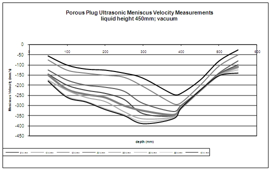
Vacuum pressure is required to account for the density differences and related pressure drop over the liquid layer. This is clarified into more detail in Appendix I .
从气体-水箱模型到氩气-铝液模型的转化我们使用了相对应的定标法则。比如,水和铝液密度的差异和在不同液位高度时相对压降必须正确地定标。同时还必须把透气砖的可湿性考虑进生成气泡的模型中。产生的结果将显示出如何通过定标调整影响精炼的过程。为了说明密度不同和压降随液面分层现象我们需要借用抽真空压力。
4.11 Wettability: 湿润性
Others have reported about water model experiments that have demonstrated quite different behaviour of the bubbles and flow pattern of water when the wetability was changed (3). Aluminium does not wet the porous plugs. Because water wets the porous plugs, special precautions must be taken. The plug was made non-wettable with grease
有人会说透气砖水箱模型在可湿性变化时只能呈现出的气泡活动和液体流线谱不同于实际情况。但实际情况是透气砖表面不会被铝水渗透,这取决于透气砖表面孔隙大小和铝水的表面张力。但尤其要注意的是,水是可以渗透进去透气砖的,而油脂性溶剂对透气砖是不可润湿的。
4.12 Experimental set-up: 建立模型:
A rectangular water model (dimensions: 1m x 1m x 1m) was built. In the model a porous plug from the cast-house was mounted. Because the construction of a scaled plug is difficult, a real plug is used. In the actual furnace, multiple porous plugs are used. On average there is one porous plug on each square meter, which justifies the choice of the water model dimensions.
建立一个一立方米的安装有透气砖在底部的水箱模型。我们使用了实际应用的透气砖,在铝熔炼保温炉内实际上是多个透气砖同时使用。平均分布计算大概一平方米面积布置一块透气砖,与水箱模型尺寸相近。
According to the scaling laws for multiphase flow, the model should be operated under an absolute pressure of 0.2 bar and a water temperature of 60°C. Due to mechanical problems the correct scaling could not completely be implemented. The pressure is reduced to 0.5 bar absolute pressure and the water temperature is not elevated because it was expected that the high temperatures would soften the seals. However, the present results show there already is a significant difference in the results at normal pressure and proves that a different means of scaling results in a different process. From experiments on a single nozzle it is known that increasing the temperature will result in slightly smoother bubbles with a more evenly distributed bubble size. This should also be the case in the liquid aluminium.
根据定标法则,在多种流速底吹下的,透气砖出气的工作压力(绝对压力)为0.2 Bar,
水温度设定为60摄氏度,由于机械原因,不可能完全准确地贯彻定标法则。
把绝对压力降低到0.5Bar,水温保持不变,因为我们希望通过提高温度让溢出的气泡更加饱和平滑。这就好比在单孔关口出来的气体会因为温度生根而变得更加平滑一些。然而,目前的结果表明,在正常压力下的演试的定标缩放气体流量实验证明不同流速时的流谱有显著的差异;从单一喷嘴的实验可知,提高液体温度,将导致气泡分布比较均匀和气泡稍微平滑。此结论也应该适用在实际铝液的情况下。
In furnace operation, the gas flow rate is in between 0.3 m? /hr up to 0.6 m? /hr at a temperature of approximately 800°C. For the scaled water situation, the gas flow rate will be a factor 3,6 higher and thus vary from 1.08 m? /hr up to 2,16 m? /hr. We have taken measurements from 0.3 m? /hr up to 2,4 m? /hr.
在实际应用中,当炉内温度为800度时,气流速度保持在0.3 m? /小时 到 0.6 m? /小时之间,对于用水做定标缩放实验的条件下,气体流量将乘以影响放大因素3.6??,因而流速范围应在1.08立方米/小时到2,16立方米/小时。我们测量从0.3立方米/小时至2.4立方米/小时之间的流谱。
4.13 Measurement techniques:
For the present study, visualisations are performed by using standard digital video equipment. With this method, different regimes in the flow patterns can easily be characterised. Additionally, an ultrasonic velocimeter was used for measurements of the fluid velocity thereby characterising the stirring action.
目前的研究是通过使用标准可视化的数字视频设备。使用这种方法,可以很容易地在归纳出不同的流谱效应。此外,超声波测速仪也被用于测量流体的速度,从而刻画的搅拌作用。
5 Results & Discussion
结论
Wettability: 湿润性:
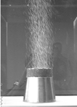
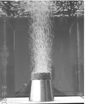
In Figure 4 the difference in the bubble formation process between a wettable and non wettable plug is shown. The close-ups of the plug in the top two photographs clearly shows the significant increase of bubble size for non wettable plugs. This can be explained by the bottom pictures. Because the liquid is not wettable to the plug, the gas phase will ‘wet’ the wall and large bubbles will form.
The resulting bubble plumes are also different. The plume narrows half way the liquid level indicating a larger liquid entrainment and thus a larger liquid displacement.
图18所示,透气砖的润湿性和非可湿性对泡沫形成差异。插在上面两张照片的特写清楚地显示了气泡体积明显随着非可湿性透气砖显著增加。这可以由底部图片看出。因为液体是不可渗润进透气砖的,气相将“湿”在墙上,大气泡会形成。
由此产生的流谱图线也不同。羽缩小一半的液位显示一个较大的液体夹带,从而较大的液体位移。
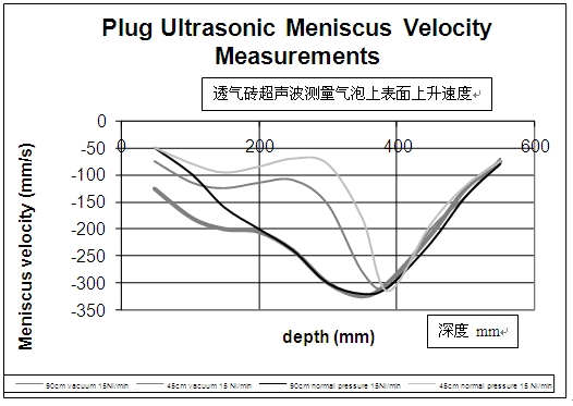
Figure 18
